Wednesday 8 December 2010

Evaluation of group work


In our group, group meeting was held about once a week in average. During a group meeting, basically we just demonstrated what we had done in the past week and made sure everything had been carried out gradually and successfully.  As we agreed in a group at the beginning, each of us would carry one scene to work along, and generally speaking, each of us has done fairly equal amount for this group work. 

Henry had been working with his part of animation, plus the sound effect and connection work for the final movie;

Matthew created the outer environment of the house for the beginning and ending part besides his own radio modeling;

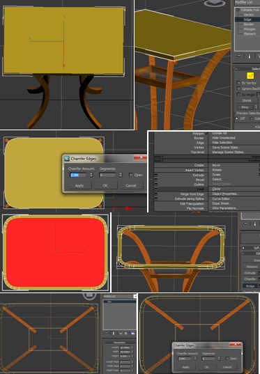
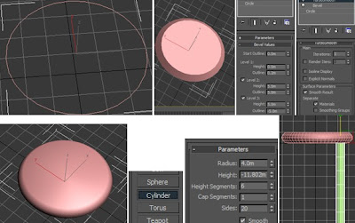
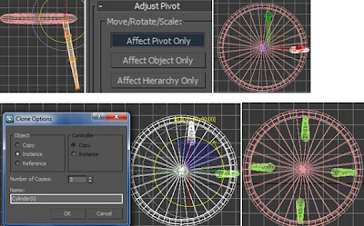
Regarding my contribution, apart from attending group meetings regularly, I also basically produced my own radio animation with an emphasis of the functionality of each button (but didn't have enough time to put all sound effects for the buttons). Also, I’ve created a room template with some furniture as well as the animation throughout the room.

Moreover, I tried to do some research work on radio history at the beginning in order to obtain more information how radio has been produced; also, the research of how to produce an attractive radio animation, which are the ads links of radio transformation posted earlier, after viewing the existing videos, we had a clearer clue of what we were going to do specifically for the radio animation. 

From my point of view, I like the radio that I’ve created the most, which I spent most of the time on it, in particular, the appearance, materials and textures. It looks so stylish and similar to the real Bush TR-82 model. Also, the button animation of the radio itself is cool!  Regarding to the group member’s work, I like the idea of showing a landscape of Essex at the end from the top view as well as the sound effect when playing the radios.

I believe that everyone has done a good job and personally, I have enjoyed very much in this module, I am proud that I have mastered new skills besides the ones from the lectures, which encourage me a lot. Last but not the least, it was really enjoyable to see the fellow students’ work in the classroom at the end of the semester, I think , to certain extent , we are all inspired with new ideas for our future work on 3d. Thanks to the lecturer's hard teaching of the lecturer and amazing video shows…

Tuesday 7 December 2010

Demonstration of new skills

The new skills I’ve mastered are:

1. Use Loft to create an innovative shape for an object, such as the examples of curtains and the table, and this method is based on creating a Spline; also, the way how to make curve by using NURBS Curves in regard to the curtain;

2. Personally speaking, Lathe modifier works similar to Loft, but it is still - quite new for me to try. The examples are of the coffee cup and the plate;

3. When I tried to created a room, I didn't realize that I could use all the existing tools to do it – no need to create a box to mimic space of a room, I can just use ‘Wall’, or ‘Window’, or ‘Door’ to automatically create them, moreover, there are plenty of functions, for instance, how to control the extent of open the door and window.

4 Use Boolean to embed one object to another is appealing for me too, take the radio buttons as examples, they look perfect;

5. In addition, some material assignment settings are new yet useful for me to learn, such as the material effect of glass, liquid, metal, etc.

Friday 3 December 2010

Final stage work

Lighting experiment before rendering

It is necessary to experiment with different lighting settings before take the whole scene to render. Also, it is very important to know what kind of lighting effect we want to have in each scene. For our group, we decided to use Omni for the room, but Skylight for the outer environment.  What are shown below are the experiment of the lighting settings with Omni.


Therefore, after having been experimenting with various setting of the Omni light, a decision of only one Omni light has been made with the following details, which looks more realistic and is currently applied as final resolution for the scene.


The animation
As is agreed in the group, each of has one scene of animation to produce and I am working basically for the second scene, the animation of the 50’s radio. The animation was made on the basis of the timeline by changing the lens or the target of camera, or by repositioning the object in the scene.

The overall timeline in scene two goes like below:

Outside of the house--> move camera towards the window--> open the window--> camera goes into the room (show all the objects in the room) -->(start to give a close-up to each object) camera moves towards the picture frame --> close-up to chair, coffee and egg --> eventually close-up to the radio

The main part of the animation is to show the functionality of the radio, which starts with the play button, and then the pause-play button, and then the volume-controller button, and then channel-controller button, with a stop button at the end to stop the music in the backdrop. Therefore, the sound effect plays a significant role in the radio animation and makes the animation livelier!

The animation for scene two is shown below:


Sunday 28 November 2010

Some food

A cup of coffee
First of all, the cup is initially made by lines. To start with, created the shape with the details as shown below, make sure all the vertices are set to smooth.


Apply Lathe modifier and set the parameters as below, so a rough cup shape is formed.


Add the handle by using line tool again and remember to tick for the Rendering. 

 
The same method as creating the cup, Lathe modifier is applied to the plate creation as well.


Add a teaspoon by starting with a box, convert it to Editable Poly and modify its shape similar to a spoon, and then apply TurboSmooth modifier.


Apply metal material for the spoon and the details are shown below.

 
Now it is time to add some coffee in the cup. Due to the shape of the cup, coffee is made with a Cylinder. Apply material as shown below.


A new technique adopted here is changing the Turbulence of the noise as well as applying Mapping to Shrink-wrap Environment in order to create the liquid effect of coffee.


Here comes a cup of coffee!


The eggs
Basically, the egg is created by a Sphere, before creating a cracked egg, clone two more eggs like the original one.


Select one of the eggs, clone and scale it down in order to have the shell of the egg. Apply Shell modifier to the outer cylinder and convert it to Editable Mesh. Select Polygon and drag some parts (as shown below) away from the other one, so that the egg is cracked!

Follow the same way to have more details of the egg by adding a few more pieces of shell fragments.


The container for egg—a nice basket
Start with creating a smooth line and apply Array method under Tool, set Array Dimensions ID to 25 and other parameters shown below, then a basic basket shape is formed.


Add a Circle on the top, set the parameters as below under Rendering, place the eggs in the basket, so the work is almost done.
 

Apply materials for the shell as shown below, the noise material plays an important role here.


Another material for the inside part of the egg is added: 

 
Apply material to basket:


So here is a basket of eggs!


Thursday 25 November 2010

Furniture and stuff


Create a table 
Start with the table leg first by creating a rectangle and a curve with Line, make sure the curve is smooth by its vertex.

 
Use the loft method to get the following shape.

 
Clone three more of the existing shapes in order to create four legs for table.

 
Add a surface for the table as to create a lower layer. Delete the polygon in the middle with a box instead; apply the following material to the box, so that it will look like a glass table with wooden table frames. 

 
Select the Edge of the box and apply Chamfer to 2.00 to have the following shape. Delete the middle polygon ad Bridge the edges. Create another Box again and place it in the middle, apply the same glass material as above. So the table is done.


Create a chair  
Create a chair by starting with the seat. First of all, draw a Circle and apply Bevel modifier by setting the following parameters, after that, apply TurboSmooth. Add a Cylinder to begin the work of chair leg.


Apply FFD 4x4x4 modifier in order to scale the Cylinder to a specific shape like below:


 Select the cylinder and adjust its Pivot, move it to the centre of the seat, the purpose for doing this benefit what I am going to do the later work. So now start to Clone three more cylinders around the seat by rotation tool. As is shown, there are four chair legs are created with the same distance to the centre and to each other.


Mirror two of the cylinders and move them upwards as to create a part of the back of the chair.

 
Draw a line between these cylinders, select Vertex and choose Smooth to form a smooth curve. Set the parameters under Rendering as below, so the line becomes more concrete. Clone five more lines to complete the back of the chair.


Afterwards, apply different material to the chair according to the details shown below:

 
At the end, do some further adjustment for the seat due to the stretched material at the edges, so the UVM Mapping modifier is adapted to avoid this problem.

 
So, the chair is done!


What is more…
A picture frame is added on the wall in order to occupy the room, in particular, it makes the room more like a ‘home’ when the camera zooms into the window.  It is basically made of ChamferBox,  then convert it to Editable Poly. Apply two Bitmaps in the material editor - one is for the picture while the other one is for the frame. At the end, apply UVW Mapping modifier to adjust the layout of the material assigned on the object.


A picture frame is done!


Assign materials to the room
 
Wallpaper 

Brocks
Floor/ carpet
Door & window
 
Apply UVW Mapping modifier to each object to assure the material has been assigned properly, then the basic environmental stuff work out as below:


Tuesday 23 November 2010

Create a room

Building up a room

First of all, create a wall in top view with Wall tool under the AEC Extended under command panel, but before that, make sure the Grid Points has been ticked under the Grid and Snap Settings, as it assure the wall goes straight and is easier to see the joint part with grid point on. Adjust the shape of the wall by vertex, then a basic wall is done.


Add a window
Create a window with Casement tool under the Windows under Command Panel with the following parameters. Set the casement to “ Two”, so that there are two window glasses, set Open value to 0%, meaning the window is closed while 100% means window is entirely open. The reason why I chose this type of window is because it looks more like the one from 50’s.


Add a door
Create a Pivot under Doors. To be honest, door creation is the difficult part, as I got problem with having the door embedded into the wall, so when I tried to open the door, I could still see the wall in it. Therefore, as finally I ended up with having the following settings, then the door worked well.


Add the floor
Here the floor was added by using line tool; follow the edge of the wall to draw the line and Close Spline at the end. Again, make sure the Snaps Toggle is on, so that the line will be drawn straight, which also makes it easier to join two points together. Convert the line to Editable Poly, then the floor with a specific outline has been created. Clone it to have the roof, due to exactly the same shape between floor and roof.


Add curtain
The curtain is basically done with loft method. Start with create three different curves with Point Curve tool under NURBS Curves as shown below, and then click on the button “NURBS Creation Toolbox” under NURBS Curves, a small window pops up, under this window, click the button “Create U loft curves” at the right bottom, then a basic window outline is formed, adjust the shape again by Point. Afterwards, add a pole (for hanging the curtain) on the top of the window by creating a cylinder.
 

Mirror the existing curtain to have other side one now.